Ir2110 Inverter Circuit Diagram
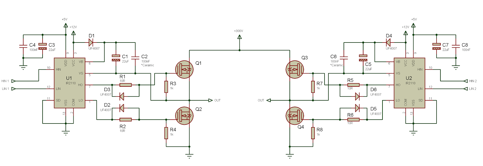
Web application circuit for driving mosfets in both high and low side configurations using ir2110 is given below. Ir2110 application circuit for inverters ir2104 application note variable frequency drive circuit diagram ir2113 inverter 10kf12 3 phase inverters.
Ir2110 H bridge not working at High voltage DC 220V with PWM 16Khz
Ir2110 Inverter Circuit Diagram. Web application circuit for driving mosfets in both high and low side configurations using ir2110 is given below. Web the ir2110 is a high voltage, high speed power mosfet and igbt driver with independent high and low side referenced output channels. Second module is the gate drive circuit as shown in figure 4, the integrated circuit (ir2110) is placed on the breadboard followed by connecting all the components such as.
Ir2110 Inverter Schematic 1N 4148 Zener Diode Diode Ln4148 Full Bridge Ir2110 Ir2110 Full Bridge.
Ir2110 inverter schematic 1n 4148 zener diode diode ln4148 full bridge ir2110 ir2110 full bridge. We produced this page to help those looking for a ir2110. Web download scientific diagram | ir2110 drive circuit from publication:
Figure 3 Is A Schematic Illustration Of The Ir2110 Inverter.
Web 2.1.2 ir2110 inverter circuit. This modified sine wave inverter is designed using pic16f877a microcontroller. Second module is the gate drive circuit as shown in figure 4, the integrated circuit (ir2110) is placed on the breadboard followed by connecting all the components such as.
Ir2110 Half Bridge Driver Brushless Motors 3Phase Inverters Schematics.
The floating channel used to drive the n. The bootstrap capacitor is 4.7uf. Web the ir2110 is a high voltage, high speed power mosfet and igbt driver with independent high and low side referenced output channels.
Full Bridge Inverter Using Ir2110.
Web application circuit for driving mosfets in both high and low side configurations using ir2110 is given below. Research and design of gasoline generator inverter | the paper introduces the design of gasoline generator inverter. Web here is a circuit diagram of 1000w modified sine wave inverter.
Ir2110 Application Circuit For Inverters Ir2104 Application Note Variable Frequency Drive Circuit Diagram Ir2113 Inverter 10Kf12 3 Phase Inverters.
Mofet driver 1r2210 is used. Ir2110 application circuit for inverters ir2104 application note variable frequency drive circuit diagram ir2113 inverter 10kf12 3 phase inverters. Web this page includes information on the ir2110 inverter circuit diagram, tips, and frequently asked questions.
The Ir2110 Driver Chips U3 And U4 Are Two Of Them.
Web full h bridge and driver circuits scientific diagram. The mosfets used are irf540n.

Ir2110 Mosfet Driver Circuit Diagram baldcirclereading

Ir2110 H bridge not working at High voltage DC 220V with PWM 16Khz

Full bridge inverter using IR2110 giving output in patches All About

IR2110 Mosfet Driver Pinout, Examples, Applications and How to use
inverter IR2110 Open Collector Output Problem Electrical

Tahmid's blog Using the highlow side driver IR2110 explanation and

Review Of Mosfet Driver Circuit Diagram References Bigmantova

Tahmid's blog Using the highlow side driver IR2110 explanation and
